Case study · RDE-2
How RDE-2 was designed.
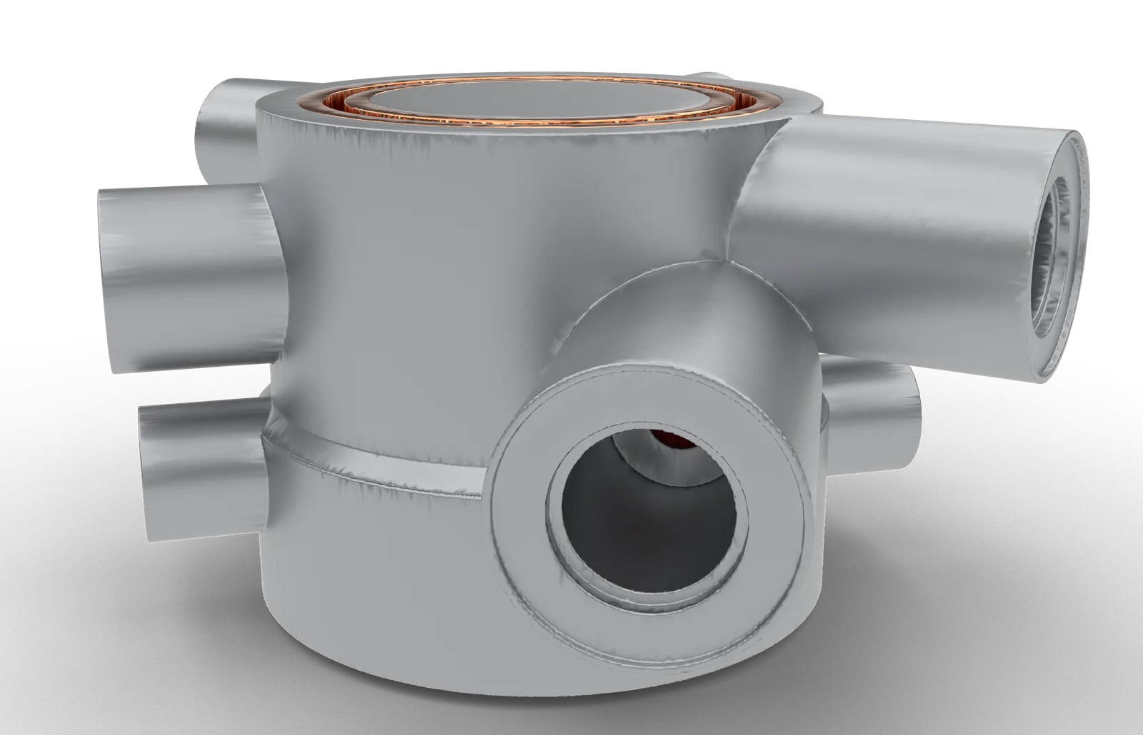
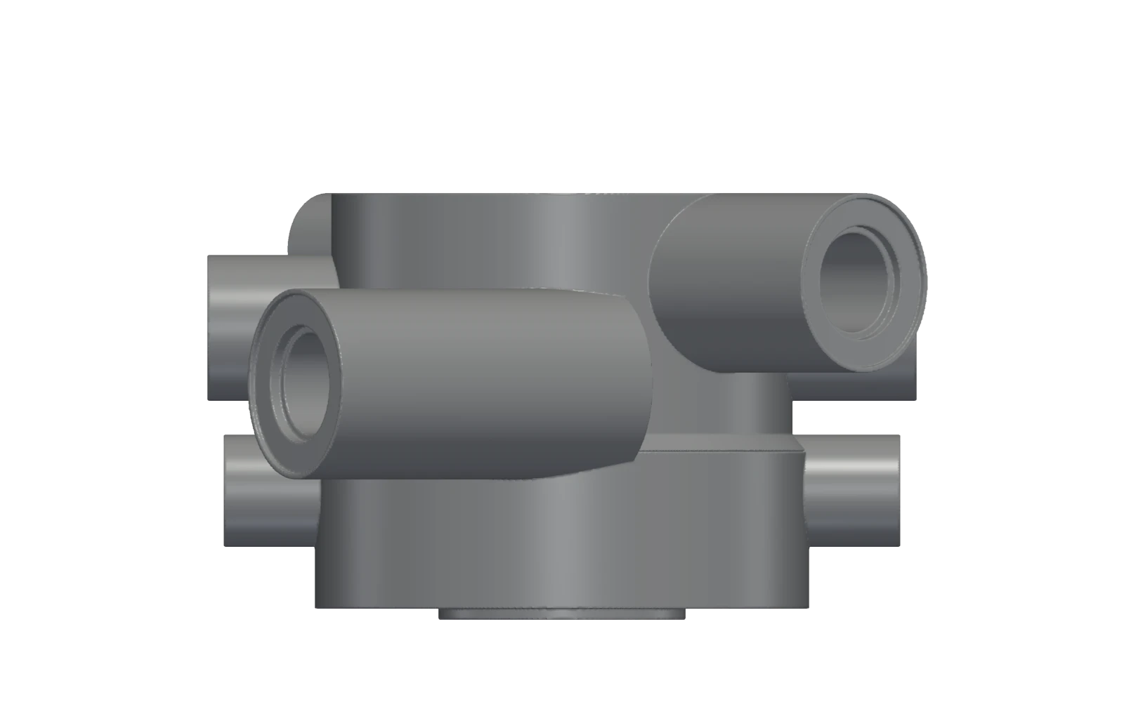
A methane/oxygen rotating detonation engine, built as a research demonstrator. It is roughly 38 mm long and 44 mm across (about 1.5 × 1.7 in), or about 64 × 72 mm including its ports. This page covers the process: what we set out to do, how the work is reviewed, and how each step is checked.
Design goals
- A compact combustor made entirely by additive manufacturing.
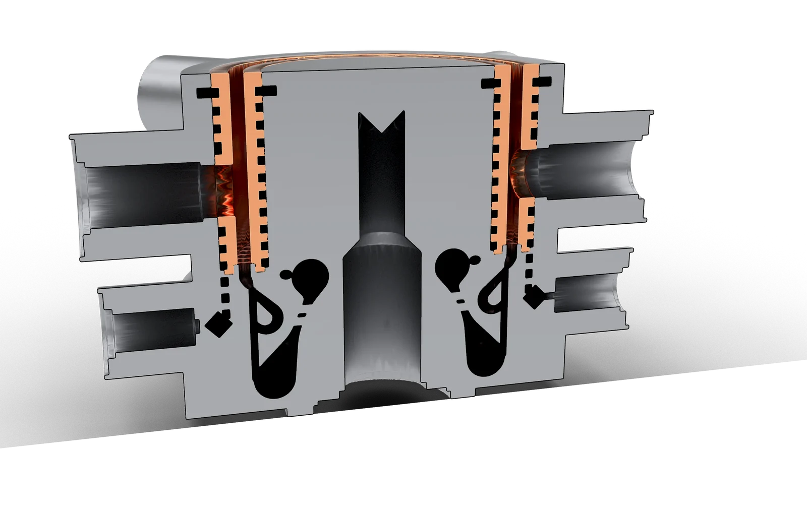
- Dual regenerative cooling: both propellants cool the walls before they are injected.
- An injector developed and checked in the same design loop as the rest of the engine.
- The current iteration is a two-part build with a standard mount.
A collaborative human + AI process
An engineer develops the design with an AI design agent. The agent writes and runs a code-driven geometry generator. Every iteration ends in a design review of a native 3D model, not a screenshot, and nothing new is generated until the engineer gives the go-ahead.
Each review produces specific changes. The step from v0.1c to v0.1d alone carried ten agreed changes, from the mounting style to how the fuel inlet enters the part. Lessons from each round are written down as design rules, so the next iteration starts from a better place. The v0.1d build passed all of its automated manufacturability and connectivity checks, with zero failures.
A multi-step design and test approach
- 01
First principles
Detonation properties, scaling, cooling break-even and printability limits set the design point before any CAD.
- 02
Generated geometry, checked automatically
Flow-path connectivity, wall clearances and trapped-volume checks run on every build.
- 03
Preliminary cold-flow CFD
An injector element was simulated in cold flow across a wide range of flow rates, in both directions, switching to a compressible solver where the flow requires it. These are early, preliminary results, not hot-fire data.
- 04
Mesh sensitivity check
The same case was run on coarse, medium and fine meshes to see how much the answer depends on the mesh. This is a sensitivity check, not a mesh-convergence study.
- 05
Benchmarking against published work
Results were compared with openly published designs. That confirmed our assumptions and led to five corrections.
- 06
Automated simulation runs
Simulations run on in-house hardware through an automated pipeline, so results come back without files being copied by hand.
Iteration timeline
- v0.1
First-principles design point
- v0.1a–c
Generator, automatic checks, review loops
- v0.1d
Two-part build, model review, 0 check failures
- CFD 1a
Preliminary cold-flow sweep and mesh check
- Benchmark
Compared with published work
Qualitative. Versions v0.1a–c are grouped.
Technical details are withheld. Propulsion data may be subject to Canadian and US export controls.